This site is being phased out.
Image Sequences
Contents
Overview
Our objective in this article is to show that the method of processing Grayscale Images applies - with minor modifications - to other single parameter images. Recall the main idea:
Any image is represented as a combination of binary images.
This time we start with a collection of binary images and show how they are produced from real life images.
In this chapter the method is developed for 2-dimensional images with 1 parameter. In other words this is simply a sequence of binary images. We will refer to then as image sequences. The main examples are the following.
- Gray-scale 2D images. Here the parameter is the gray level. Given a threshold T, the corresponding frame contains all the pixels with gray level lower than or equal to T. More generally, the parameter may be any numerical value (pressure, temperature, density, etc).
- Binary 2D movies. Here the parameter is time or frame number. An image sequence can also be obtained from a still binary image by moving a frame around the image, zooming in/out, tilting, etc, or drawing on it. (See Object tracking.)
- Binary 3D images. Here the parameter is the number of the slice of the image. Given a cross-section of the image, the frame consists of the pixels corresponding to the voxels in this slice.
- Binary images (and especially point clouds) modified by multiple applications of morphological operations. Here the parameter is the step number in the process. The most typical operation is that of dilation.
We are interested primarily in topological events.
Below one can compare an example of the sequence of frames of a gray scale image and an example of the sequence of frames of a binary movie.
The algorithm in Binary Images partitions each frame of the image into black and white regions. These regions are bounded by 0- and 1-cycles respectively. The areas and perimeters of these regions are computed. In addition, the cycles in every frame are related to the cycles in the previous and next frames via a graph. So far this appears exactly similar to Grayscale Images. Observe, however, that in the case of gray scale images (#1) the (dark) objects in the sequence always grow. In the case of dilations applied to a binary image (#4), the objects also grow. But in the case of erosions, the objects will shrink. In #2 and #3 the objects may expand in one area and shrink in another. Therefore, the cells are not only added as previously but also removed. This also affects the graph. Indeed, 0-cycles not only merge but also split, while 1-cycles not only split but also merge. This will be discussed shortly.
Recall that the more important part of this graph, called the frame graph, consists of the connections of cycles in the current frame to the ones in the next. Its links reflect merging and splitting of cycles as we move from frame to frame.
Based on this information, lifespans of cycles are computed. The last step is image simplification. Simplification will remove unwanted items, such as noise, from the image. The user simply indicates the ranges of sizes and contrasts of the objects he considers to be noise. The method removes all objects with these characteristics. The topological characteristics of both the original and the simplified image are computed.
The step of the algorithm
At every step of the run through the frame, a pixel in PrevFrame is compared to the corresponding one in CurrFrame. If the colors are the same, skip to the next step. If the color changes from white to black, execute AddCell. If the color changes from black to white, execute RemoveCell. Every time the geometry of the image changes, the list of cycles and the graph, the numerical characteristics of the cycles, and the Betti numbers are updated.
// processing the frame

for(k=0;k<dim1;k++) // start the (k,l) pixel
for(l=0;l<dim2;l++)
{

// if the new pixel is black and the color of its position is white

if( CurrFrame[l+dim2*k] == 1 && PrevFrame[l+dim2*k] == 0 )
   AddCell(k,l);

// opposite

if( CurrFrame[l+dim2*k] == 0 && PrevFrame[l+dim2*k] == 1 )
   RemoveCell(k,l);

}

Simplify(frame); // optional
The AddCell command is exactly the same.
The RemoveCell command first removes the pixel itself by creating a node for the 1-cycle made of its 4 edges. Then it removes each of these 4 edges one by one provided it is not an edge of another pixel. RemoveEdge either creates one node if it is a merge or two nodes if it is a split. The links for these nodes come from the SplitCycle and MergeCycles commands described below. Next, each of the 4 vertices of the pixel is removed unless it is a vertex of another pixel. RemoveVertex removes the corresponding node from the graph.
void RemoveCell(int x1, int x2)
{
int edge[4];
edge[0]=x1;  edge[1]=x2; edge[2]=1; edge[3]=0;

   struct Cycle *Cycle0 = CreateCycle(edge);

   Cycle0->Dim = 1;
   Cycle0->Length = 4;

       AttachCurrCycle( Cycle0 );    // make current

   edge[0]=x1;   edge[1]=x2;  edge[2]=1;  edge[3]=0; GiveCycle(edge, Cycle0);
   edge[0]=x1+1; edge[1]=x2;   edge[2]=0;  edge[3]=1; GiveCycle(edge, Cycle0);
   edge[0]=x1+1; edge[1]=x2+1; edge[2]=-1; edge[3]=0; GiveCycle(edge, Cycle0);
   edge[0]=x1;   edge[1]=x2+1; edge[2]=0;  edge[3]=-1; GiveCycle(edge, Cycle0);

   TraverseCycle(edge,Cycle0);

   betti[1]++;

     edge[0]=x1;   edge[1]=x2;   edge[2]=1;  edge[3]=0; RemoveEdge(edge);
     edge[0]=x1+1; edge[1]=x2;  edge[2]=0;  edge[3]=1;  RemoveEdge(edge);
     edge[0]=x1+1; edge[1]=x2+1; edge[2]=-1; edge[3]=0;  RemoveEdge(edge);
     edge[0]=x1;   edge[1]=x2+1; edge[2]=0;  edge[3]=-1; RemoveEdge(edge);

    int point[2];
    point[0]=x1; point[1]=x2;  RemoveVertex(point);
      point[0]=x1+1; point[1]=x2; RemoveVertex(point);
           point[0]=x1; point[1]=x2+1; RemoveVertex(point);
               point[0]=x1+1; point[1]=x2+1; RemoveVertex(point);

}
By removing a node (or a cycle) from the graph we understand either the physical removal from the memory or simply marking it as non-current. Creating a node (or a cycle) means allocating memory for the data.
AddVertex is exactly the same.
void RemoveVertex(int point[2])
{ int edge[4];
      edge[0]=point[0]; edge[1]=point[1]; edge[2]=0; edge[3]=0;
   int i,j;
      // test for the presence of an edge containing this vertex

   for(i=0;i<3;i++)
   for(j=0;j<3;j++)
   {
int temp[4]={point[0],point[1],i-1,j-1}; // starting at the vertex...

       if ( (i!=1 || j!=1) && GetCycleN(temp)!=0)
               return(0);
// the array is NULL everywhere including border

int temp1[4]={point[0]-i+1,point[1]-j+1,i-1,j-1}; // ending at the vertex...
        if ( ( i != 1 || j != 1 )
             ( point[0]-i+1 < dim1 && point[1]-j+1 < dim2 )
           GetCycleN(temp1) != 0)

           return(0); // the array is NULL everywhere including border
   }

struct Cycle *Cycle0 = GetCycle( edge );

   DisconnectCurrCycle( Cycle0 );     RemoveCycleInfo( Cycle0 );

     GiveCycle( edge, NULL ); // invisible

   betti[0]--;
}
Problem Create a simple interface for the program without simplification and run it. The output should be a sequence of the Betti numbers of the frames. Create a simple binary movie and verify the correctness of the Betti numbers.
Adding and removing edges
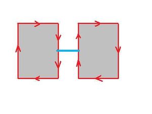
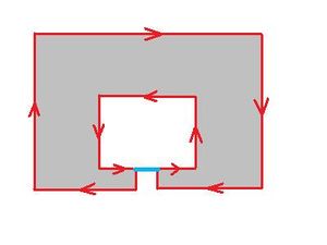
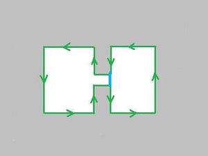
Next, we describe under what circumstances MergeCycles and SplitCycle are executed. In Binary Images there are 3 cases. Now there are 6 cases. The first three are about adding edges, so they are the same as before and AddEdge is the same as before. We repeat those for convenience.
(a) If the edge being added connects two different 0-cycles, they are merged. MergeCycles with these two 0-cycles as the input creates a new 0-cycle. Its birth-frame is that of the older of the parents. The 0-Betti number goes down by 1.
(b) If the edge being added connects a 0-cycle to itself, this cycle is split. SplitCycle with this cycle as the input creates a new 1-cycle and a new 0-cycle. The birth-frame of the former is the current frame and the birth-frame of the latter is that of the father. The 1-Betti number goes up by 1.
(c) If the edge being added connects a 1-cycle to itself, this cycle is split. SplitCycle with this cycle as the input creates two new 1-cycles. The birth-frames of these are that of the father. The 1-Betti number goes up by 1.
void AddEdge(int *edge)
{
   int back[4]; Reverse(edge,back);
        // pick up the cycle node from the next edge!= edge
int forward[4]; StepForward(edge,forward,0);
       struct Cycle *CycleForward = GetCycle(forward);
int backward[4]; StepForward(back,backward,0);

       struct Cycle *CycleBack = GetCycle(backward);

int dim = CycleForward->Dim;

if (CycleForward != CycleBack )
        MergeCycles(CycleForward, CycleBack, edge, back, 0);
     // (a): 0 is the dimension of the new cycle
else
      SplitCycle(CycleForward, edge, back, 1 , dim);
     //
(b) or (c): 1 and dim are the dimensions of the new cycles
}
(d) If the edge being removed is a part of a 0-cycle and a part of a 1-cycle, these cycles are merged. MergeCycles with these cycles as the input creates a new (same) 0-cycle. Its birth-frame is that of the 0-cycle. The 1-Betti number goes down by 1.
(e) If the edge being removed is a part of two 1-cycles, the cycles are merged. MergeCycles with these cycles as the input creates a new 1-cycle. Its birth-frame is that of the older of the parents. The 1-Betti number goes down by 1.
(f) If edge being removed is only a part of a 0-cycle, the cycle is split. SplitCycle with this cycle as the input creates two new 0-cycles. Their birth-frames are that of the father. The 0-Betti number goes up by 1.
void RemoveEdge(int *edge)
{     int back[4]; Reverse(edge,back);
       struct Cycle *CycleForward = GetCycle(edge);
        struct Cycle *CycleBack    = GetCycle(back);

       GiveCycle(edge,NULL);
       GiveCycle(back,NULL);

int forward[4]; StepForward(edge,forward,0);
     // ..so that we can step forward to a new edge!=edge
int backward[4]; StepForward(back,backward,0);

int dim = abs( abs(CycleForward->Dim - CycleBack->Dim) – 1);

if (CycleForward != CycleBack)
  MergeCycles(CycleForward,  CycleBack, forward, backward, dim);
           // (d) or (e): dim is the dimension of the new cycle
else
     SplitCycle(CycleForward, forward, backward, 0, 0);
           // (f): 0, 0 are the dimensions of the new cycles
}
Merging and splitting cycles
Next, we describe how MergeCycles and SplitCycle are executed. Computation of lifespans is necessary.
Recall that for SplitCycle the numbers dim1, dim2 are the dimensions of the new cycles. As a result, a cycle of dim1 or dim2 is gained.
void SplitCycle(struct Cycle *Cycle0, int *edge1, int *edge2, int dim1, int dim2)
{
       struct Cycle *Son1 = CreateCycle( edge1 );
       struct Cycle *Son2 = CreateCycle( edge2 );

           TraverseCycle (edge1, Son1);                  // Dim, Length, Area are found

           if ( Son1->Dim == dim1 ) Son2->Dim = dim2 ;
           else                     Son2->Dim = dim1 ;

           if ( dim1 == dim2 )
                 Son1->Birth = Cycle0->Birth ; // (c):1-1 or (f):0-0
           else if ( Son1->Dim == 0 )  // (b):1-0
                       { Son1->Birth = Cycle0->Birth ; // old 0-dim
                             Son2->Birth = frame ;   // new 1-dim
                             }
                 else
                       { Son2->Birth = Cycle0->Birth ; // old 0-dim
                             Son1->Birth = frame ;   // new 1-dim
                             }
           Cycle0->next[0] = Son2;
           Cycle0->next[1] = Son1;

         DisconnectCurrCycle( Cycle0 );  // not current
         AttachCurrCycle( Son1 );  // make current
         AttachCurrCycle( Son2 );  // make current
         if ( dim1 == 0 && dim2 == 0 ) betti[0]++;
         else           betti[1]++ ;

}
Recall that for MergeCycles the number dim is the dimension of the new cycle. As a result, a cycle of dimension dim is lost.
void MergeCycles(struct Cycle *Cycle1, struct Cycle *Cycle2, int *edge1, int *edge2, int dim)
{
   int DIM1 = Cycle1->Dim;
   int DIM2 = Cycle2->Dim;
       struct Cycle *Son = CreateCycle( edge1 );
           Son->Dim = dim;

   if( DIM1 == DIM2 ) //   (a) or (e)
   if( Cycle1->Birth > Cycle2->Birth )
       Son->Birth = Cycle2->Birth ; // birth frame of older parent
     else   Son->Birth = Cycle1->Birth ;
   if( DIM1 != DIM2 )// (d)
   if( Son->Dim == DIM1 ) // birth of same-dim parent
       Son->Birth = Cycle1->Birth;
   else
       Son->Birth = Cycle2->Birth;

           betti[dim]--;

     Cycle1->next[0] = Son;
     Cycle2->next[0] = Son;

             AttachCurrCycle( Son );  // make current
             DisconnectCurrCycle( Cycle1 );  // not current
             DisconnectCurrCycle( Cycle2 );  // not current
}
As cycles merge and split, a new cycle inherits the birth-frame of the (older) parent of the same dimension. However, other schemes may be appropriate depending on the application. For example, the birth-frame of the new node may be the weighted sum of those of the parents with weights equal to their sizes.
The lifespan based simplification of image sequences
Recall, the output of the algorithm after every frame has been processed is the collection of all current cycles. Next, the Evaluation command either accepts or rejects each cycle. First, the current cycles with low area are marked as inactive (or rejected and not recorded into the graph of the simplified image). The result is a simplified frame graph.
An important characteristic of a cycle is its lifespan. A component emerges at frame B (birth) and merges with the surrounding area at frame D (death); a hole emerges at frame B and is filled at frame D. The total lifespan is D - B. In the present version, the current lifespan, N - B, where N is the number of the current frame, is used to decide whether the feature should be plotted.
- In case of a gray-scale image, this is the contrast of the feature.
- In case of video, this is how long the feature has been present on the screen. As noise is likely to have a short lifespan, it is removed.
- In case of a 3D image, it is the thickness of the object. Therefore, lifespan-based simplification removes “thin” features. A better way to simplify it is to remove 3D objects of low volume rather than low thickness. A connected component of the 3D image is represented by a connected component of its frame graph. Therefore, the volume of a component can be computed by adding together all areas recorded in the corresponding nodes for all frames.
- In case of dilation of a point cloud, the lifespan of a 1-cycle is (roughly) the minimal diameter of in the feature, D, minus the largest distance between any point and two of its nearest neighbors, B. Therefore, incidental holes are removed.
The user can customize this program to gain more control. First, he can create his own image sequences from still images - gray scale, color, increasing or decreasing resolution, erosion, dilation, as well as any combinations of them. He can also create his own Evaluation function by choosing his own integrands, or his own settings.
In a movie, a given cycle and all its descendants can be plotted in the same color throughout all frames to help track an object. For a 3D image, if the cycles in each frame are plotted in the corresponding level in 3D, they render the surface boundaries of the components of the image.
To simplify the image we evaluate cycles. To evaluate the cycle, below we consider its area and length and its lifespan. Here, as before, the minimal area, minArea, and the minimal length, minPerimeter, are the same for all cycles independent of dimension or location. These are the main simplification settings.
unsigned long minArea = 0; // min area of the cycle
unsigned long minPerimeter = 0; // min length of the cycle
int minLS = 0;  // min lifespan of the cycle
Recall that to visualize a gray scale image, active 0-cycles are filled with the current gray level while the active 1-cycles are filled with white. Suppose the image sequence comes from a video. Then, for each frame, a similar recoloring procedure that switches between black and white is carried out. For a 3D image, the same is done for each slice before they are combined into a 3D picture.
Simplification and visualization of a point cloud is carried out as follows. First it is thickened. It is done until the set is connected (or the Betti numbers fall within the desired range), or for as many steps as set by the user. This is followed by a topology preserving erosion. The result is a binary image.
The topology preserving version of the algorithm is given below.
int curb[2];
currB[0] = betti[0];  currB[1] = betti[1]; //current Betti numbers

// if the new pixel is black and the color of its position is white

if( CurrFrame[l+dim2*k] == 1 && PrevFrame[l+dim2*k] == 0 )
  {
   AddCell(k,l);

   if( TopPres != 0 && (currB[0] != betti[0] || currB[1] != betti[1] )
     { RemoveCell(k,l); CurrFrame[l+dim2*k] = 0;     }
   }

// opposite
if( CurrFrame[l+dim2*k] == 0 && PrevFrame[l+dim2*k] == 1 )
   {
   RemoveCell(k,l);

   if( TopPres != 0 && (currB[0] != betti[0] || currB[1] != betti[1]) )
           { AddCell(k,l);    CurrFrame[l+dim2*k] = 1;       }
   }
Running through the list of current cycles gives us the total number of cycles of each dimension, up to simplification. This provides the count of objects within the image sequence.
long Betti[2] = {0,0}; // total number of cycles,4 this is in the
                               // beginning of the program
. . .

struct CycleNode *Node = LastCurrCycle;

   while( Node != NULL )
   {
       if( Evaluation(Node) == 1 && Node->Birth == frame )
            Betti[Node->Dim]++;
          Node = Node->linkB;
     }
Problem Add to the program the simplification procedure and the ability to choose the simplification settings. The additional output should be the simplified image and its Betti numbers. Verify the correctness of these numbers.
Problem Add to TraverseCycle the option of recording the edges in a separate file. Plot them.
Problem Add the option of simplifying the image based on the combination of area, perimeter, and contrast. Experiment with the program.


